
This product does not have a specific scale associated with it. It will appear in our product lists regardless of what scale you have selected . Please check the description (if available) to ensure that it meets you needs.
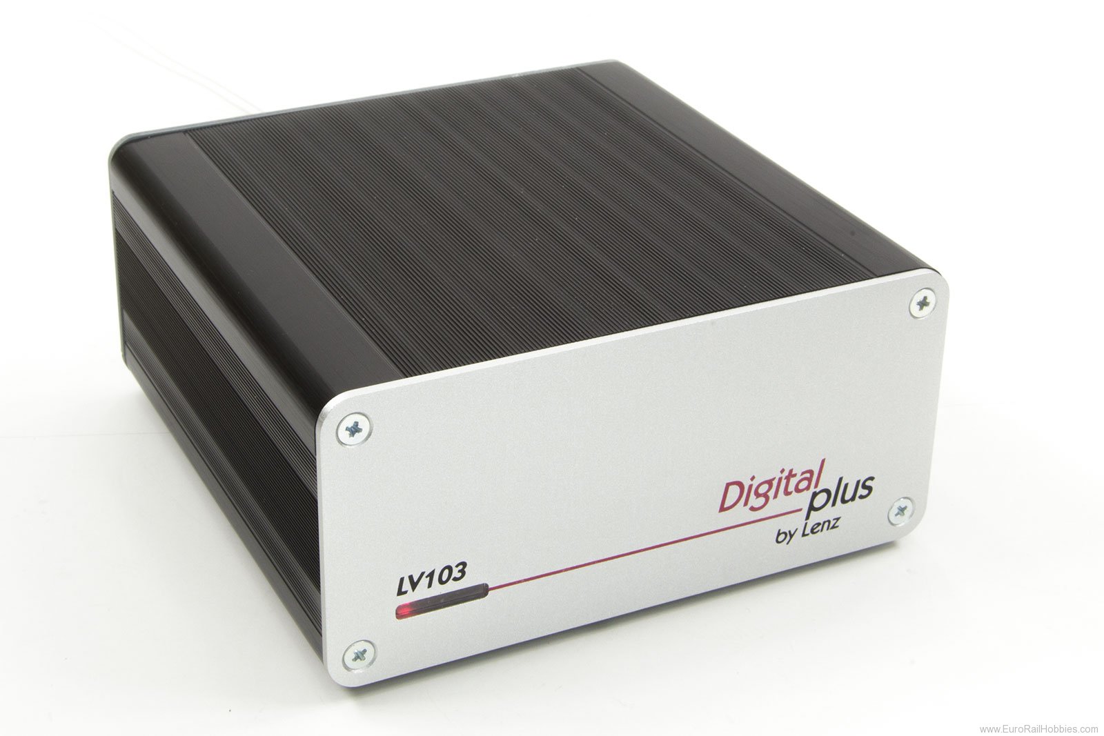
The LV103 is designed to meet the safety requirements and conditions for operating a model railway. If required, the track voltage and output current can be individually adjusted and set to suit the circumstances; the maximum current provided is 5 amps. The factory setting is an output voltage of 16V and a maximum current of 5A. The LV103 is set for RailCom operation and has an integrated global RailCom detector. Dimensions: 120 x 55 x 120 mm